


Errors in control devices must be quickly detected and corrected. This TechPaper highlights basic error detection and correction concepts and explains what are known as “patterns”: standard solutions in software architecture. It will then examine how these are integrated into an AUTOSAR software architecture in real-life projects.
In recent years, there has been strong growth in the number of electronic control units (ECUs) and their functions in vehicles. New technologies, particularly in the Driver Assistance sector, mean that functions are becoming more complex. Additionally there are increasing demands on hardware performance. Where 40 MHz single-core processors used to be sufficient in the past, multi-core processors with three-digit clock rates are now being used. In order to manage the complexity involved, standardization alliances such as AUTOSAR or GENIVI developed software architectures that have become established aspects of many ECUs. Safety standards such as ISO 26262 and IEC 61508 contain further guidelines on developing control units according to functional safety criteria. However, they do not prescribe specific solutions, in order not to limit the system designer in creating an optimal solution.
New assistance functions and increasing complexity also means that there is a growing demand for handling errors that can occur on control units. To date, most of the systems are based on fail-safe architectures: if an error is detected in the ECU with a high probability, the function will be switched off; full control is returned to the driver, who is then informed.
Thus, the safe mode for many assistance systems is where they are turned off, combined with a warning to the driver. The driver can then react properly, e.g. by driving manually, by stopping the vehicle or providing maintenance. This type of error handling is safe and is often a frustrating experience and the vehicle is perceived as unreliable. However, as soon as functions for partially automated or fully autonomous driving are affected, this type of error handling is no longer sufficient to ensure the safety of the vehicle occupants. In this case, if an error occurs, full or at least degraded functionality needs to be available for a reliable operation. Such systems are called fail-operational.
Fail-operational systems are already established in other safety-relevant areas, such as atomic power plants and aviation. The design of these systems is mostly comprised of redundant partial systems combined with monitoring mechanisms that mask or replace the path that is causing an error. The first step is usually simple redundancy combined with a voting mechanism as shown in Figure 1.
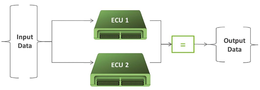
The system implements two redundant channels and the voting mechanism can detect that an error has occurred in one of the ECUs. However such a system can only be fail-safe as the voting mechanism only detects dissenting results, but it cannot determine which of the ECUs failed. The voter would then trigger the transition to the safe state.
The next approach is triple modular redundancy or 2oo3 systems as shown in Figure 2.

This pattern has three redundant ECUs combined with a voter. When only one of the ECUs produces a dissenting result the dissenting ECU is considered as failed. But the system can continue with the remaining two ECUs. Such 2oo3 system are established in industries where system reliability is crucial for safety such as avionics or system failure is a significant cost factor such as in chemical plants.
However the number of newly deployed air planes or chemical plants is limited compared to the automotive domain where many millions of systems are produced and deployed every year. Triple modular redundant systems are very expensive to develop and to produce compared with current fail-safe systems. Other factors such as weight and power consumption also need to be considered: there are physical limits of power consumption in the vehicle network and more weight leads to increased fuel consumption. Hence, there is a need for suitable technical solutions that provide a balance between market and customer expectations regarding price and reliability of fail-operational systems.
Another approach is a 1oo2D system as shown in Figure 3.
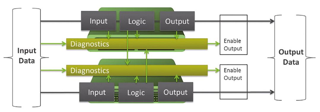
This pattern is based on a 2-channel system where each channel has a high diagnostic capability and can detect and signal its own failure in most cases. In the remaining cases there is per definition a master ECU and the voter favors the master.
If one of the two channels fails, the system can disable the failing channel and continue to operate temporarily with only one channel. Having only one channel the system effectively loses its fail-operational capability and needs to return to fail-operational as soon as possible. Additionally external monitoring systems need to be ready for complete system failure. In many cases the established handover to the driver might be sufficient.
Simulations using techniques from reliability engineering such as Markov chains can be used to compare the reliability of 1oo2D systems with 2oo3 systems. The crucial factor in this comparison is the level of diagnostic coverage of each individual ECU. This applies to random hardware failures as well as to systematic failures in the implementation of the function in software.
Excursion: Error detection in ADAS systems
Most driver assistance functions, such as Lane Assistant, form a decision based on a large number of input values, including camera images (Figure 4). In this case, the decision comes in the form of driver warnings or active steering interventions.
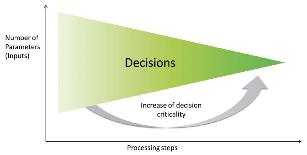
Many driver assistance functions process extensive volumes of data, often from multiple sensor systems. This can be, for example, to produce redundant paths for safety reasons. These data are prepared, checked for their feasibility and merged to functionality. Errors in processing or decision-making become more critical the further they are toward the right in Figure 4, because the data and decision redundancy declines. The mechanisms for error detection are identical to those in fail-safe systems. This is how checksums, plausibility tests, threshold analyses or filtering of transient values are used on the data flow. Additionally, there are error detection mechanisms that monitor system integrity, and conduct system tests on run-time if required. These system tests become necessary if the operating time increases, due to the growing use of assistance and automated functions in driving situations. This means that transient errors can occur more frequently.
Safe State and partial recovering
As described in the chapter before, 1002D system can continue operating in one channel mode for a short period of time. A potential solution to decrease the one channel operation time would be to map established design patterns for high-availability, safety-relevant software on individual cores of multi-core processors, or to use other ECUs to take over functions. The latter would also involve changes to existing E/E vehicle architectures: Functions are dynamically distributed to multiple control units and additionally switched on or switched off. This system reconfiguration required access to sensor and actuator on demand e.g. as a service that might be requested in the in-car network. The reconfiguration might be statically preconfigured while using static AUTOSAR systems or completely dynamic in adaptive systems.
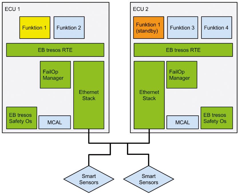
Figure 5 shows an architecture containing a replacement function. Function 1 is active on Control Unit 1 during the normal state. In the event of an error, the function shall be migrated to Control Unit 2. Based on whether it is running in cold or hot standby, partitions must be started. If required, functions that are less important can be turned off, such as Function 4. This means that resources can be used efficiently without needing available computing power.In addition to own state monitoring, the replacement control unit must also be monitored when migrating functions between the control units. This is the responsibility of the FailOp Manager. The challenges for this design will be to ensure that detection and switching are rapid, and to prevent two active parallel functions (split brain).
The AUTOSAR software architecture is configured statically, including the operating system. In order to integrate dynamic replacement mechanisms into a static architecture, AUTOSAR offers several options: To switch functions to a replacement mechanism, it must be possible to connect and disconnect them. AUTOSAR offers four different mechanisms for this, for example:
- RTE mode switches
- Starting and stopping alarms and tasks to influence the performance of functions
- Starting and stopping OS applications that in turn display a group of OS objects (for example, Task and Interrupt).
To enable functions and monitors to perform independently, the operating system must provide a partitioning mechanism. The EB tresos Safety OS Multi-Core operating system provides in addition to the required partitioning mechanism, which has already been certified up to ASIL D, the option to start and stop partitions. This is because it has been reproduced using OS applications. This enables efficient functional migration to a control unit.
Autonomous driving perspective
The current fail-safe architectures only enable partially autonomous driving. In the event of an error, they require human attention, and the vehicle driver continues to be part of the vehicle’s operation. Using a combination of established concepts from other industries and automotive standards such as AUTOSAR, we can, in fact, find solutions to develop high-availability control units. Such solutions can be based on Elektrobit’s experience gained from a wide range of projects in various domains such as driver assistance systems, combined with products that include EB tresos Safety OS, without compromising on standards such as AUTOSAR. Only these types of control units can form the basis for autonomous driving, both because they react to errors independently and because they enable the system to continue operating.
Download our free version of EB tresos evaluation package
The EB tresos evaluation package includes all of the tools necessary for you to develop ECU software in compliance with Classic AUTOSAR software architectures: EB tresos AutoCore, EB tresos Studio, EB tresos AutoCore OS
Download the evaluation package for free today and start configuring AUTOSAR-compliant software immediately.

Authors

Rudolf Grave
Former Head of Product System Architecture

Alexander Much
Head of System Architecture

